Read the previous entry for this topic: Researching commercially available options and gathering ideas
UPDATE: I never got around to building this project, instead I bought a Nektar Pacer MIDI Foot Controller which has pretty much all the functionality that I was planning for this build. You can read more about it here.
Note: this entry is still a work in progress..
As mentioned in the previous entries, the Bridge Controller will hold the brains and circuitry required to read from the footswitches and convert those signals into standard MIDI messages.
I'll break up the electronic circuit into different components and I'll go through the design requirements and solutions given to each one. The components are:
- An Arduino Nano (ATmega328) microcontroller
- 12 digital inputs to read the switch states
- 5V power regulator to regulate from a 9V DC barrel jack (to use the same Boss PSA power adaptors) to 5V
- MIDI IN opto-coupled circuit, to be used to soft merge and pass through messages to the MIDI OUT
- MIDI OUT circuit
- 2 5V mechanical relays to simulate a CTL1+CTL2 pedal output
Arduino Nano
The Arduino Nano uses the same microcontroller as the popular Arduino Uno, the ATmega328 chip, but comes in a much smaller package. There's not much to say about the Arduino that hasn't been already written on the internet.
I will be using the basic Arduino Nano 3.x version with headers, and I'll place some female headers in the PCB in order to be able to remove the Arduino if needed, or to replace it if something goes wrong. There are some newer versions that include Bluetooth BLE (Low Energy) such as the Nano 33 BLE or Nano 33 IoT which give me some ideas for a 2.0 version of this controller.
Here are some specs of the Nano from the official Arduino website that will be useful later on:
- 22 digital I/O pins
- Maximum current of 40mA per I/O pin, with a total maximum of 200mA through all of the pins.
- Power consumption is about ~19mA
Digital Inputs from the Footswitches
Reading the status of a switch is one of the most basic functions for a microcontroller, but still, I'll first contextualize about the different type of switches and the things that should be considered in order to take reliable readings from the footswitches. The only thing that I'm skipping here is debouncing, since I will cover that on the software side.
Types of Switches
A switch is one of the simplest electrical elements and in its most simple version it's a cable that can be either disconnected (open: does not allow for current to flow through) or connected (closed: allows a current to pass).
There are many different types of switches with many different characteristics for every application, but I'll concentrate on two of them:
Action Mode determines the behaviour or state of the switch after it has been pressed. - Momentary action means that the switch makes contact (closes) only when it's pressed, and as soon as the force is removed the electrical contact opens. - Latching action means that the switch changes its state (from open to closed, and vice versa) each time it's pressed and maintains its current state until it's pressed again. In other words, if the switch is open and you press it, it closes and stays closed until you press it again. It toggles from one state to the other.
Polarity determines the default state of a momentary switch, and consequently its behavior when it's pressed.
- In a normally open (NO) configuration, the switch is open when unpressed (default, normal or resting state), and it closes when it's pressed or activated.
- In a normally closed (NC) configuration, the switch is closed when unpressed (default, normal or resting state), and it opens when it's pressed or activated.
Reading a Switch State
In my design I'm assuming that all of my footswitches will be (i) momentary action and (ii) with a normally open (NO) polarity. I believe this is by far the most common type of footswitch available in the market, and many of the more complex switches can be configured in either mode anyway.
Reading the state of a switch is a simple as reading the voltage from one node of the circuit and watching what happens when the circuit closes as the switch is pressed. However, there's a catch. A switch can be open or closed, but only when the switch is closed a circuit is formed and current is allowed to flow, and a voltage can only be measured on a closed circuit. That means that something must be done to account for the open state of the switch to be able to reliable measure it.
To solve this, I will be using a configuration known as pull-down resistor. What this does, is that it guarantees that whenever the switch is open the microcontroller will read 0V (LOW). In other words, when the switch is open the circuit pulls down the voltage. However, when the switch is closed the microcontroller will read +5V (HIGH). This prevents any undetermined or floating measurement.
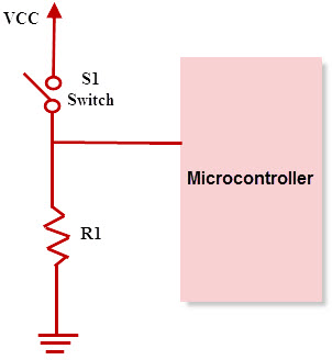
- When the switch is open, the pin is connected to GND through a 1kΩ resistor, since there is no current flowing from the pin, there is no voltage difference in the resistor and the voltage on the pin is 0V.
- When the switch is closed, a small current flows through the 1kΩ resistor to GND and closes the circuit. This also directly connects the pin to the +5V rail, thus getting a measurement of 5V in the pin.
All in all, this configuration translates to:
- when the Switch is not pressed (
open), we will read aLOWsignal, interpreted as0in the microcontroller. - when the switch is pressed (
closed), we will read aHIGHsignal, interpreted as1in the microcontroller.
Handling different types of switches and plugs
For the actual footswitches, they will be connected to the Bridge Controller using a TRS 1/4" plug. A single TRS cable can connect 2 footswitches since it carries 3 wires: one for each switch and the third as a common connector.
Following the Boss/Roland custom, they map a TRS (Tip Ring Sleeve) 1/4" plug as:
- Tip: mapped to the B switch
- Ring: mapped to the A switch
- Sleeve: common (return for both A & B)
The word "Jack" is used for the female socket, while "Plug" is used for the male connector
While this is a neat solution to wire two switches over a standard cable, it also presents an interesting problem when plugging a TS cable (Tip Sleeve) since there's no Ring in the plug. This means that the electrical connector that we'd expect for the A switch is merged into the Sleeve, so the device will always read the A switch as closed.
Since I want to be able to plug single footswitches (for example basic sustain pedals) as well as dual footswitches using the same TRS jacks, this means I have to apply some extra logic. The type of connector (TRS or TS) could be detected upon power-up if we assume that the switches are always NO. The logic for the detection would be:
Assuming that there are two pin inputs (D0 and D1) in the microcontroller, and they're mapped as:
- Pin D0 -> Tip
- Pin D1 -> Ring

Then:
- If D1 (Ring) is HIGH: set D0 as Input A, disable D1 and disappear the Input B
- If D1 (Ring) is LOW: set D0 as Input B, set D1 as Input A
This will require that whenever I turn on the bridge, I make sure that:
- all of the pedals are already connected
- I'm not pressing any button on any pedal
- all of the pedals have a NO polarity, since it would not be able to differentiate a NC switch from a TS cable.
MIDI
The MIDI standard was released in 1983, about 35 years ago, and it's stood the test of time since it's still widely used.
It has a couple of design
it uses a 5-pin DIN connector, but it only uses 3 of those pins.
A newer standard has __ in the last few years, which uses a standard 3.5mm TRS minijack (headphones), since it only requires 3 cables. The wiring of the 3 pins in the TRS (Tip Ring Sleeve) _ has two variants, which have been called Type A and Type B.
The device will have both a 5-pin DIN connector and Type A (the newer one) __ __ don't depend on adaptors and for future compatibility.
MIDI communicates with a sends it signals by a __ current __ , 0mA (low) and 5mA (high). Instead of voltage.
And the devices that __ are not electrically connected. Instead, they are opto-isolated.
A device could be operating at 5V __ as long as the current is respected.
MIDI IN Circuit
asdfasdfasdf
Opto-isolated which means that the input signal __ is not electrically connected to any of the __ device's
The information is transmitted by light inside the optocoupler, which creates an insulation barrier, __
In order for this to work, the input signal coming from the external device has to provide the required power to light the LED inside the optocoupler, and this is were the required 5mA in the MIDI signal spec come into play.
MIDI OUT Circuit
The __ sends power...
the Tx pin actually sinks current.
+5V GND Tx
This is actually a pretty nifty and resilient design that __ both the operating spec, as well as protecting the device from any kind of
a standard 220Ω resistor is put in both the __
Let's assume the following scenarios where either the cable is faulty or the receiving device is faulty.
- Shorting the +5V to GND, there's the Source 220Ω resistor, generating a ~23mA current. It __ in our 5V rail.
- Shorting the Tx pin to GND while Tx is low, it doesn't matter, there's no voltage differential.
- Shorting the Tx pin to GND while Tx is high, there's the Tx 220Ω resistor, generating a current of ~23mA. The ATmega328 max current is 40mA per pin, so we're safe.
- Shorting the Tx pin to +5V while Tx is low, there's the Source 220Ω resistor as well as the Tx 220Ω resistor, generating a current of ~11mA. The ATmega328 max current is 40mA per pin, so we're safe.
- Shorting the Tx pin to +5V while Tx is high, it doesn't matter, there's no voltage differential.
Those are all the possible __ operating malfunctions.
Now, under normal operation, the complete Tx circuit is:
+5V -> Source 220Ω resistor -> 220Ω resistor on the MIDI IN side -> 1.3V drop of the optocoupler LED -> Tx 220Ω resistor -> Tx pin sink

Total Current = (5V - 1.3V) / (3 x 220Ω) = 4.998mA
Just on spec!
Fault tolerance
MIDI IN to MIDI IN: there's no current at all
MIDI OUT to MIDI OUT: both circuits are grounded, ___ both should have a __
Even if there is a voltage differential between the 5V rails, and one of the Tx pins is LOW, the maximum current would be 5V / ((220Ω|220Ω) + 220Ω) = ~15mA
it doesn't affect our device since our ___ have at least 220Ω resistance between them.
Switching Relays
a small 5V
under load it ___ about 70mA. This is well over the maximum current of the Arduino's I/O pin, so we cannot handle it directly. For this, we'll need a small "buffer" stage.
The Arduino I/O pins will __ that will amplify the current to operate the relay's coil.
We need a small
Event
A simple NPN transistor operating as a buffer. I'll use the simplest design __ that still offers some security to the circuit, without worrying too much about .. this relay will never
We'll calculate for a maximum load of 100mA. Since the ___ has a base-to-collector ratio of about 1/10, we can ___ to source 10mA into the base to __ full saturation mode.
We'll only be using a base resistor, ~10kΩ ? 1k
1k in th ebase 10k in parallel between the base an the emitter
the relay has a coil inside, we need a "flywheel diode" in paralel to the coil to protect the circuit from surges when
a DPDT (double pole double throw) switch to change the "polarity" of the relay, by selecting between the Normally Open (NO) and the Normally Closed (NC) state.
Power Regulator
For simplicity, I will be using a LM7805 5V linear regulator. It's a very old and inefficient design, but that makes it very cheap and easily available. Since we are not running from a battery source.
I'm assuming a maximum load of ~300mA (~40mA for the Arduino, ~70mA for each relay, ~30mA for the MIDI circuits, ~90mA losses and other components such as LEDs, etc.)
Wattage dissipation: (9V - 5V) * 300mA = 1.2W
Under max load ~2W
Max operating temperature is around 125º C
it has a thermal resistance of 65C/W junction to air. This means that for every 1 Watt that is dissipated, the temperature raises 65º C over the room temperature.
Under our calculated maximum load the regulator would increase its temperature by 78º C over the room temperature (65C/W x 1.2W). Assuming a base temperature of 25º C, the final regulator temperature should be around 103º C when running a continuous load of 300mA.
Not great, but nothing to worry about. Nevertheless I'll be sticking a small heatsink to the regulator, but I'm not sure if it'll be of any help at all since it's all going to be inside a plastic enclosure.
The enclosure is not small, and there __
This __ will_ __ in a plastic enclosure of about
If temperature ever becomes an issue, I will need to change the enclosure to metal, and stick the backside of the regulator to the enclosure wall to dissipate heat into the box itself.
Programming
Since we'll be using the serial Tx/Rx ports in pins D0 and D1 of the Arduino to handle __ MIDI, it'll collide with __ when programming the ATmega328, since it uses those same serial connections.
There are two options to handle this issue: - Remove the Arduino Nano from the board, connect it via USB, flash it and put it back in the board. - Place a DPDT (double pole double throw) switch to disconnect the MIDI circuits from the Arduino's Tx/Rx, and then use this switch to change from "programming" mode and "run" mode, without having to physically remove the Arduino Nano.
The Final Design
Putting it all together, the final design is __
Refernces:
- Nuts and Volts